")


The current big task is the design and manufacture of all the steam and exhaust pipes. The original pipes were in no state to be reused, and many were manufactured from pipe sizes no longer available. New drawings were created, using the closest available pipe sizes, and a whole set of new flanges and lens rings designed and manufactured to suit.


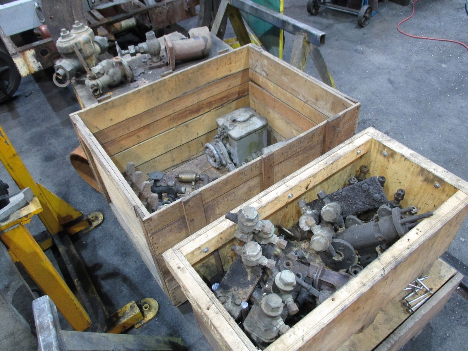
As work progresses, more and more of the original parts are required, either to be overhauled and reused, or as patterns for measurement to allow new ones to be manufactured. With attention beginning to focus on lubrication and boiler fittings, several boxes have been recovered from storage, allowing things like safety valves, top feed check valves, blowdown valve, injectors, lubricators and oil feed pots to be dismantled, cleaned up and condition checked for possible reuse.

Pipework manufacture on the engine units has also begun. Above, a newly machined flange is attached to the steam inlet on a cylinder. This gives us a fixed point to work from when starting to cut and tack together bits of pipe.
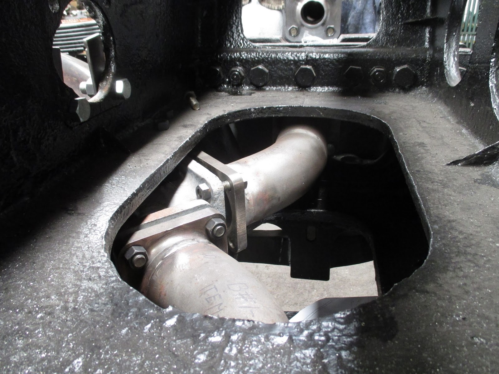
Below, the exhaust pipes have been trial fitted between the cylinders and the exhaust ‘Y’ branch, from where a pipe leads to the exhaust ball joint. Note how confined the working space is, and how access is limited by the between-cylinder stretched casting. This is why the pipes are being made and fitted now; further on in the assembly process, access will become near impossible to this area!

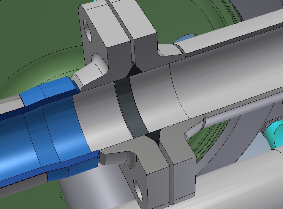
Virtually all the steam and exhaust pipe joints are sealed with lens rings, which locates in a cavity formed by recesses in two adjoining flanges. Above, a selection of different sized rings, based on the pipe diameter, and below, a section taken from the 3D CAD model showing the make-up of a typical lens ring joint.
In order for all the pipework to be complete, the flexible ball joints with connect the pipes on adjoining parts of the locomotive are required. At each end of the boiler cradle, a steam ball joint, steam pipe expansion joint and exhaust ball joint provide the flexibility famous in the Garratt design.
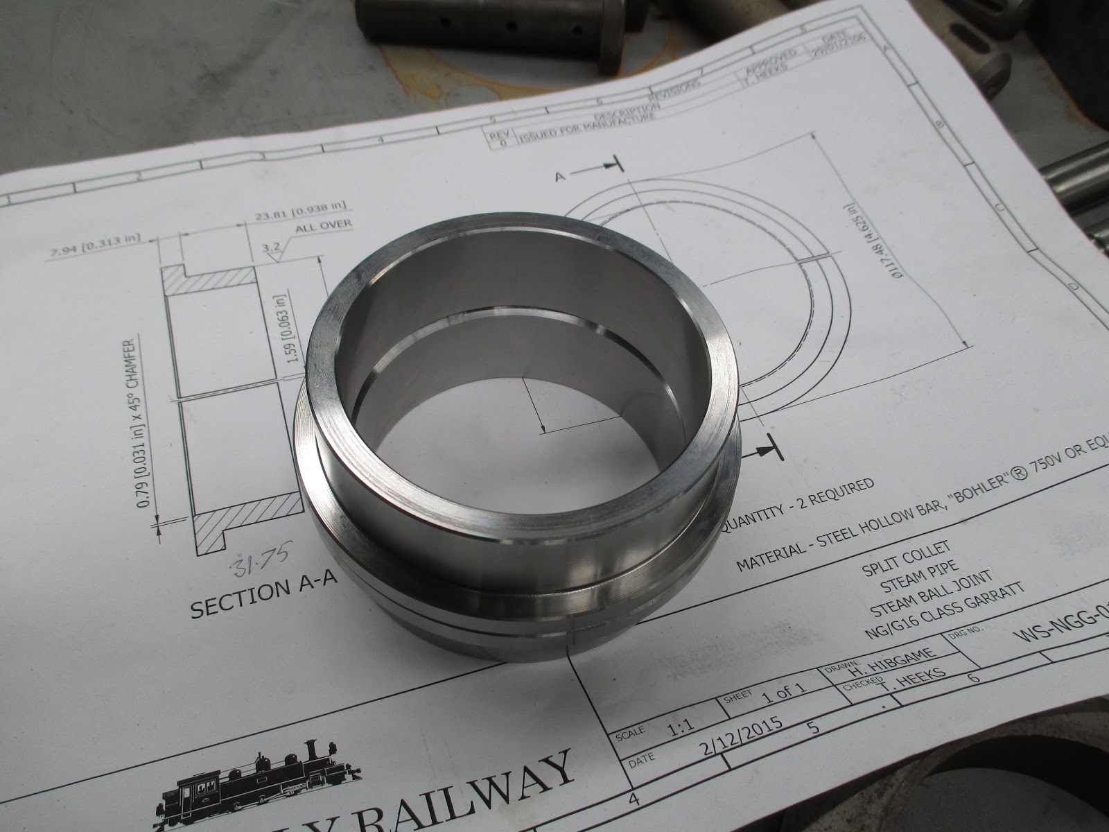
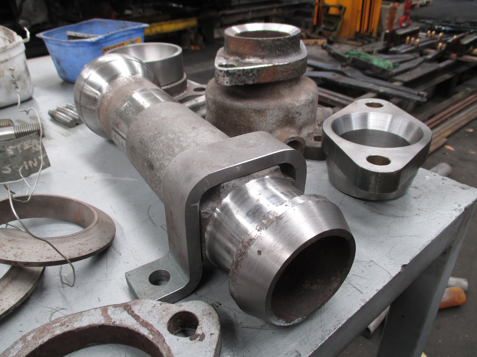
Above, a steam ball joint body has been built up and machined back to original size, surrounded by the new retaining clamp. (Below) One of the many condemned parts, in this case a split collet, has been replaced with one newly machined from the drawing.