")


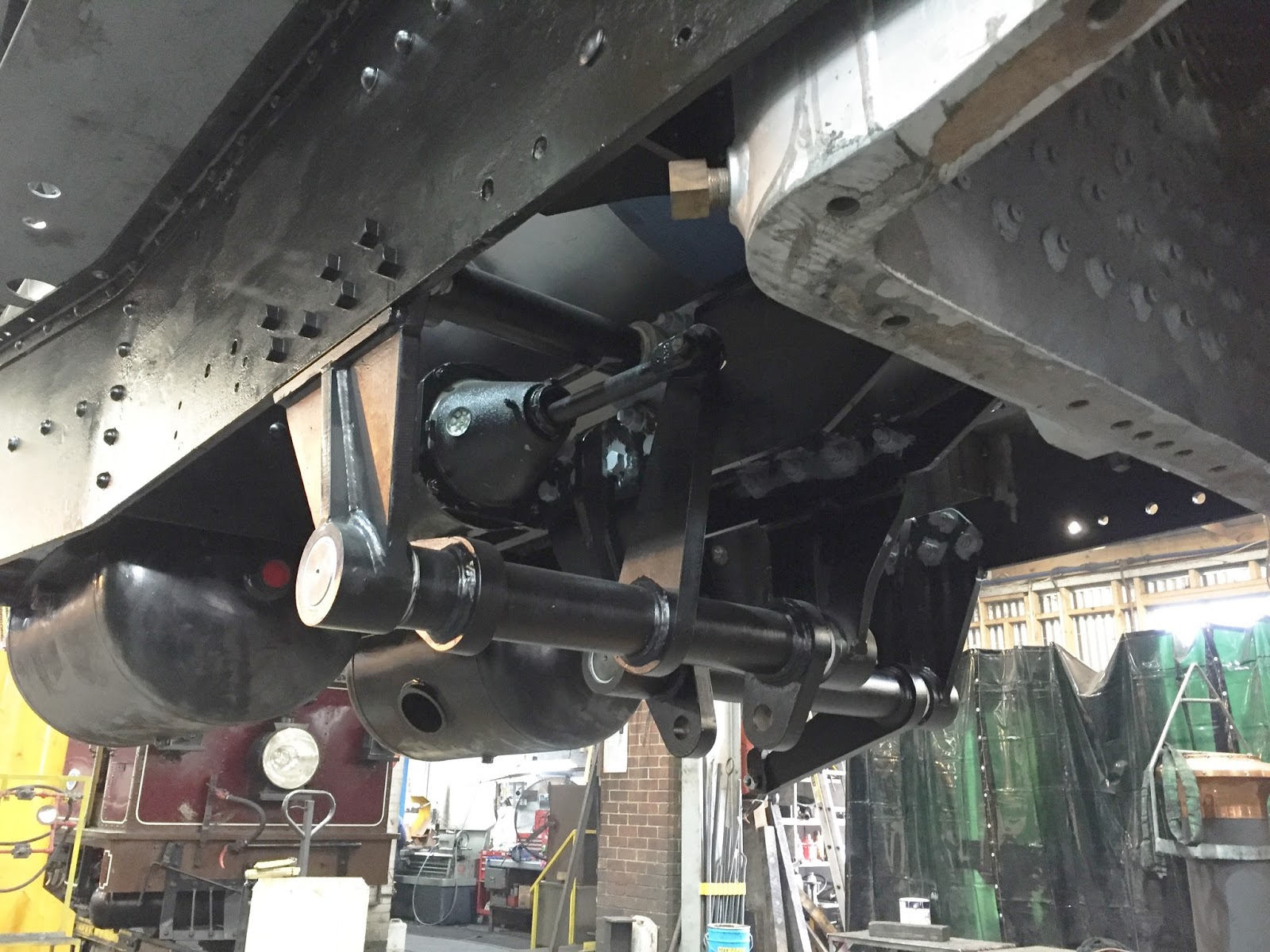
Brake hanger brackets, shafts, air reservoirs and actuating cylinders have been fitted, complete with Vesconite bearings. The next stage for the brakes is the layout and plumbing of all the pipework required to make the system work.
Riveting of the remaining boiler cradle frame stretcher and footplate brackets has been completed, and the running boards are currently being drilled ready for final fitting.


Above, the newly fabricated steam pipe that resides below the cab floor, supplying the hind engine unit; this also has a connection used to supply drifting steam from the drifting valve.
Below you can see the steam pipe ball joint mounted in position within the hind pivot casting.
All the completed steam and exhaust pipework is being painted, and the lens rings which make the seal between the pipe flanges are being lapped in.


All the new regulator components have been machined ready for assembly, including new castings obtained through the good offices of the Ffestiniog & Welsh Highland Railways, and have been trial fitted to the boiler.

Above, the original expansion links have been measured and assessed, and new bushes will be manufactured as required. The die blocks were found to be past their prime, and new ones will be machined.
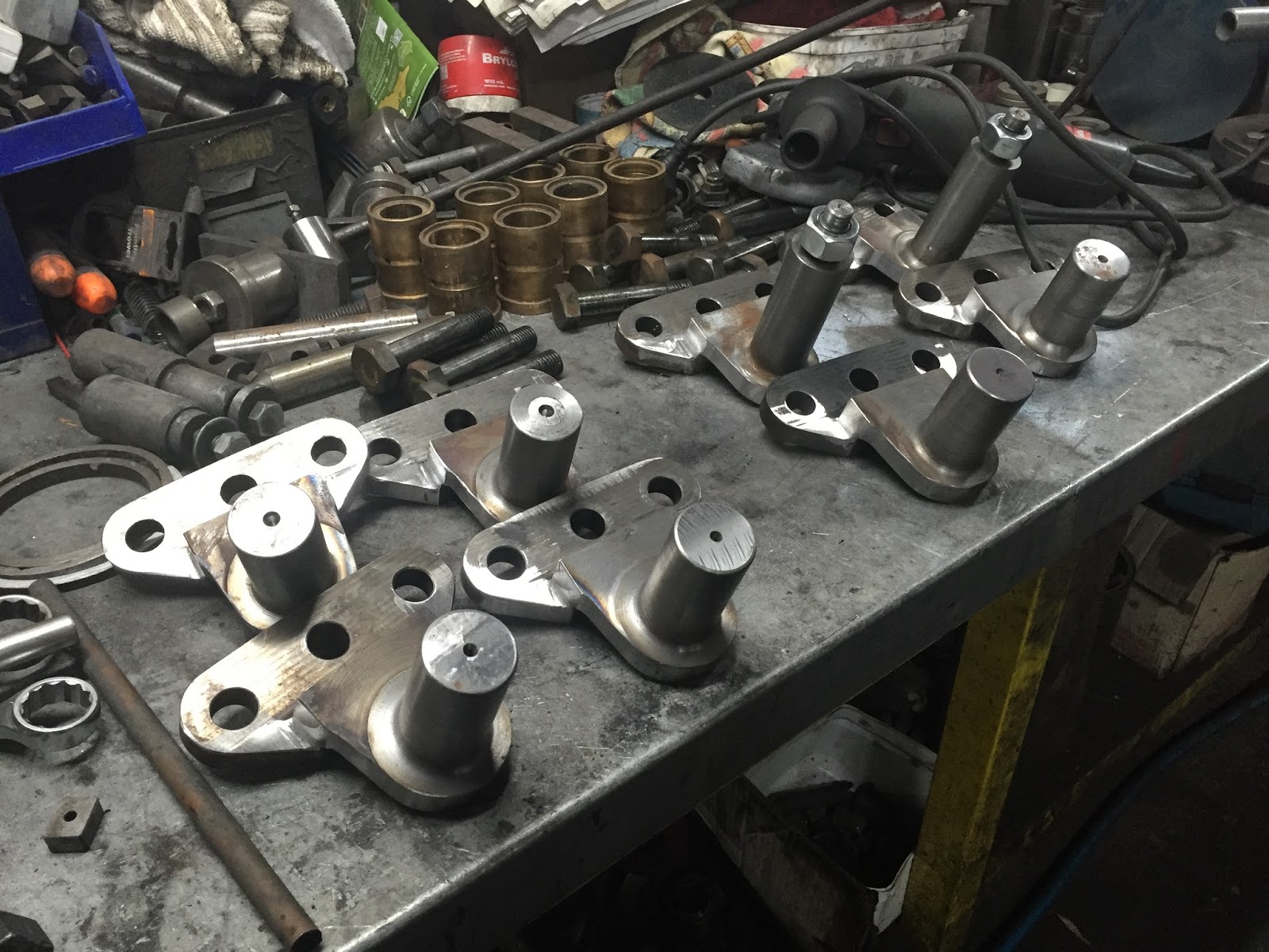
New expansion link trunnions have been profile cut and machined, ready for assembly. The trunnions are the pivots about which the expansion links rock, driven by the eccentric rods from the return crank, thereby giving linear motion to the piston valves.

The existing crossheads were condemned at an early stage, so drawings were produced, patterns manufactured, and new ones cast. These have been partially machined to accept the slipper, side liners, piston rod and gudgeon pin.
The crosshead slippers are currently having new whitemetal cast prior to machining.


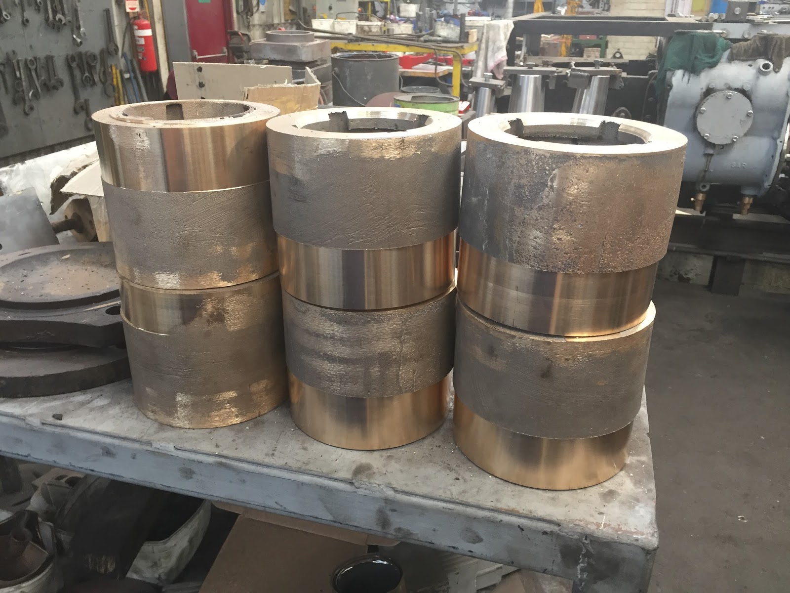
Side rod bush drawings are complete, patterns have been made and a full set of new bushes have been cast (above).
Below, rough machining has started in preparation for casting the white metal bearing faces into the bushes.

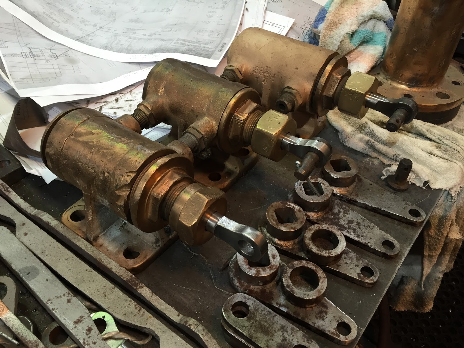
Drain cocks have been dismantled, overhauled and reassembled, in readiness for attaching to the cylinders, whilst below, the actuating cylinders for the drain cocks, front sanders and rocking grate are all being overhauled and new linkage drawn and manufactured.

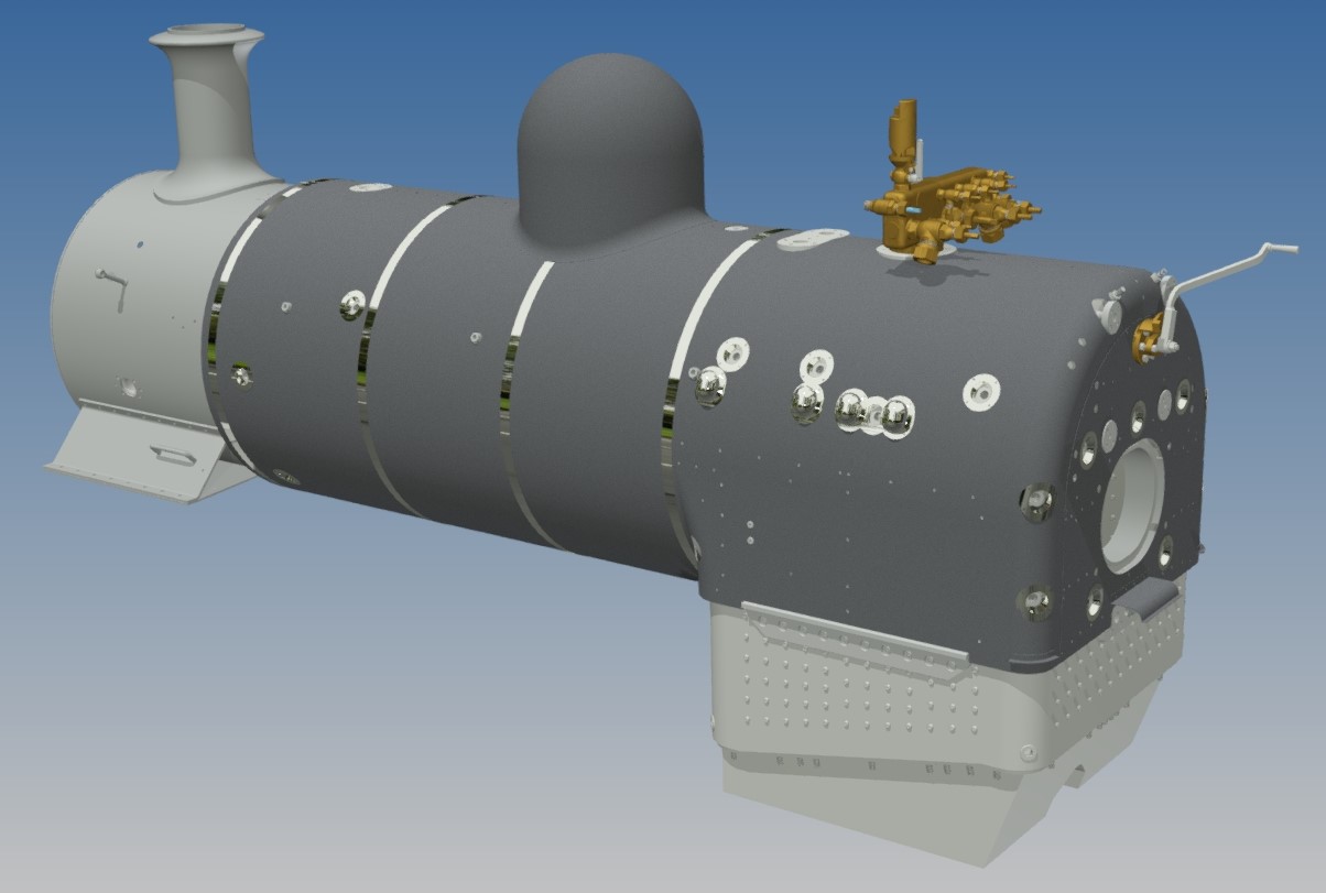
Cladding sheets for the boiler have been designed and all the sheets laser cut and rolled prior to delivery. All but 2 fitted perfectly and the incorrect ones have been re-manufactured.

The backhead corner trim from the original boiler will be re-used, having been modified to suit the new Klinger type gauge glasses, and the cladding plates redesigned to allow for a reduced number of boiler washout plugs.
The new boiler only has about one third the number fitted to the original design, and this was deemed suitable bearing in mind the quality of water available at Puffing Billy, and the effectiveness of the water treatment we use.


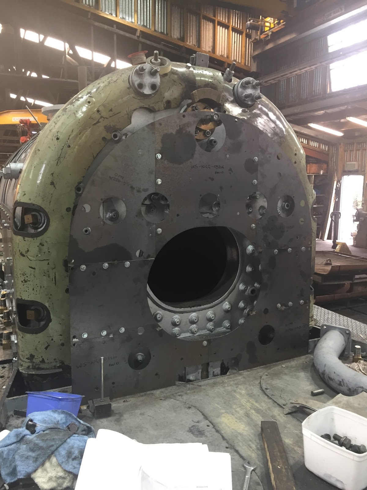
Following the re-gauging work, the motion brackets were found to be out of line, rectification of which could have been a major task, with the result that the engine units might have had to be sent out for further machining work.
After some investigation, we were able to source a mobile milling machine, which was set up mounted to each engine unit in turn, and all the rear and top faces of the motion brackets were re-machined to bring them back in line. The weigh shaft mounting brackets are currently being machined to suit.

Above, brand new spacers to fit into the pivot centres between the boiler cradle and the engine units, individually machined to size in order to ensure that both ends of the boiler cradle sit at the correct height above rail level.
The valve gear components are currently being assessed, worn holes measured and new bushes and pins drawn up for manufacture.


Above, progress refurbishing the reverser stand by the NG/G16 volunteer team continues. Drawing for a brand new screw and nut have been prepared and an order placed for manufacture.
Below, brand new machined annular ring castings for the 4 piston valves, provided by IXL Foundry of Geelong.


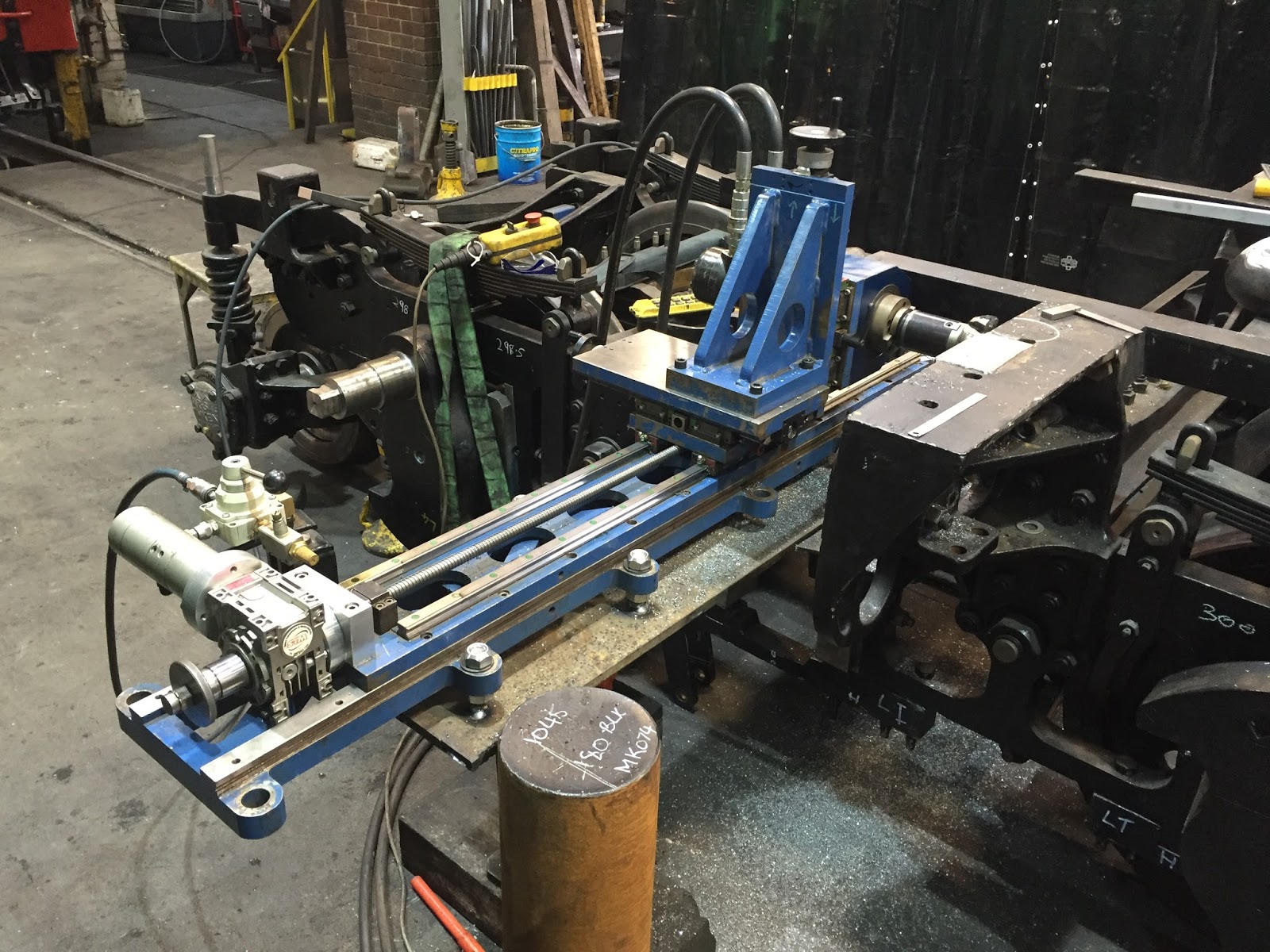
Setting up and fitting of the 4 pairs of slidebars between the rear cylinder covers and the motion bracket is currently underway, involving much machining, bushing of oversized holes and fitting of shims.
Below, the steel wire ‘string line’, which is set up to run on the cylinder centre line, allows the slide bars to be set up accurately, ensuring the crosshead and piston rod run true to the bore of the cylinder.


This stamp on one of the slidebars showing not only the SAR running number, but also the builders number and the slidebar’s location on the locomotive, in this case RHT – Right Hand Trailing.
Final setting up and welding of the water balance pipes from the pivots, alongside the boiler cradle, to the injector water feedwell is almost complete, with just the pipe joints to be finished. The valve (Centre of photo) allows the water supply from the hind tank to be isolated. There is a similar valve controlling the flow of water from the front tank, and with both valves closed, the filter in the feedwell can be checked/cleaned.

Finally, on the 9th August, the boiler cradle, complete with boiler, was married with the engine units for the first time in about 20 years. Making use of both workshop gantry cranes, the boiler and cradle were lifted and the 2 engine units rolled underneath before it was lowered into position.
Whilst there is still a lot of work to do before the engine enters traffic, this gives a good indication of the scale of the project, what has been achieved so far, and what remains still to be done.
