")

Photos from the boiler makers in Sydney have arrived showing the latest progress, and things have come a long way since last time. Above and below, the inner and outer firebox has been fitted together, the foundation ring has been tacked in place, and the stays between inner and outer are being made and fitted.
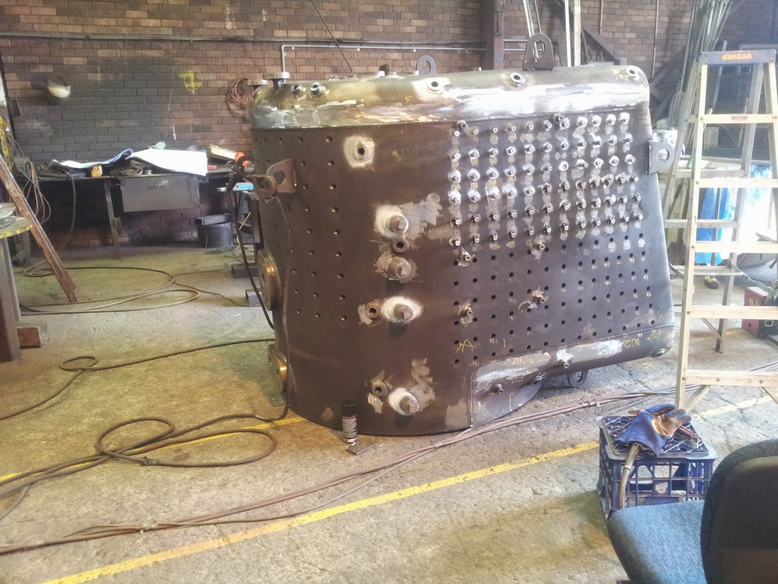

The stays have to be individually machined to length to suit the varying thickness of the water space between inner and outer firebox profiles. The stays must all protrude through the plates by a fixed amount, which is sufficient to allow for welding. They must also be positioned centrally within the clearance holes in each sheet, and to aid in location, a special jig is used (below).


Using the jig, the stays are positioned in the holes, and tack welded in place (above). Once completed, the stays are then fully welded inside and out.
The biggest weld on the boiler is that which holds the foundation ring to the inner and outer firebox sides. Once the foundation ring is in position, it is impossible to weld around the top on the ring, in the water space, so large J welds are used on the bottom (outside) to form the seal. In the photograph below, the inner firebox is at bottom right, and the outer firebox is top left. The foundation ring is the piece in the middle, with the weld preparation machined ready for the welds to be laid down.


The view on the top of the firebox (above) allows us to see the steam turret seating (left) and the safety valve seats (right). The holes in the boiler shell and corresponding ones in the turret seat are to accept the crown stays which will support the crown sheet against the boiler pressure acting on top of it.
The complete steam dome is shown below, with the boss to secure the dome cover in the center, and the vent fitting just to the right. The vent allows air to escape when the boiler is being filled with water for hydraulic testing; it is plugged once water begin to escape, and the boiler can quickly be bought up to pressure during inspections.