")
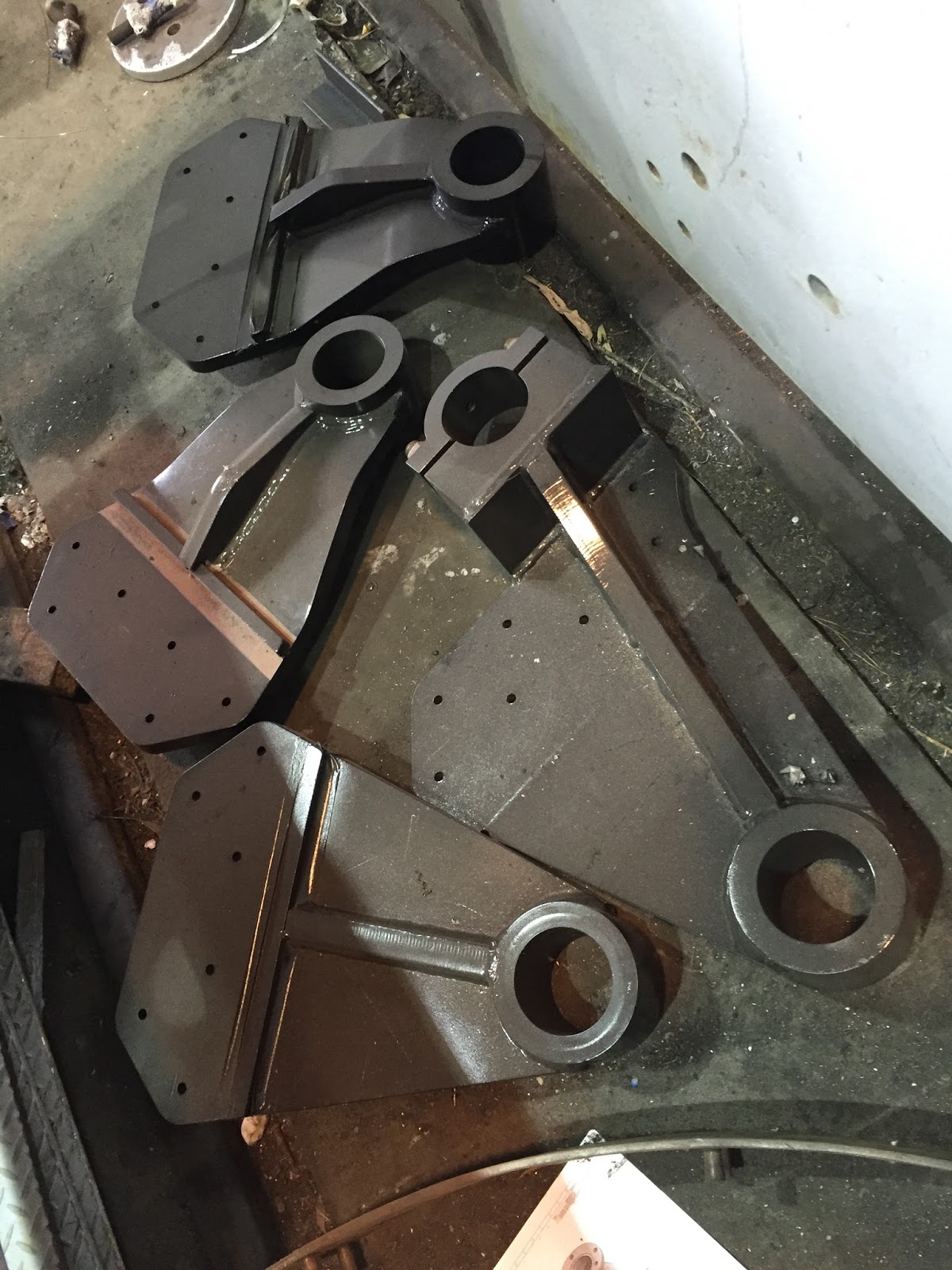
The boiler was recently removed from the boiler cradle, in order for work on the piping and brake rigging to continue. The cradle will soon be turned over for fitting of the completed brake shaft hanger brackets (above).

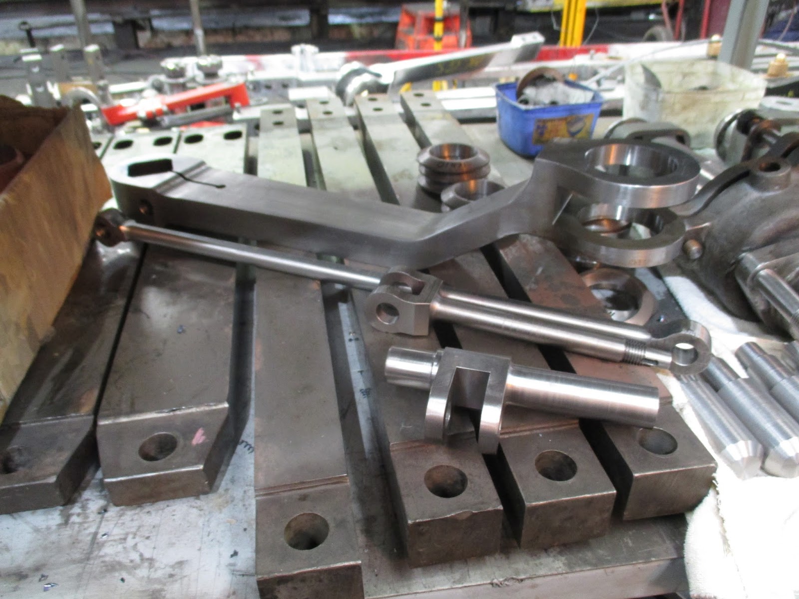
Above and below, the brake shafts are seen under construction. The shaft in the lower photograph has an extra arm; this is the shaft that actuates the rear brakes, upon which the handbrake also acts, and the extra arm links to the handbrake shaft. Originally the NG/G16’s had twin vacuum cylinders, and these have been replaced with twin Knorre Bremse air brake cylinders.


We are now into the final sections of steam and exhaust pipe being fabricated and fitted. Above, one of the engine unit steam pipes from expansion joint to cylinder block is being welded.
With the boiler removed, final adjustments and welding up of boiler cradle steam and exhaust pipes can take place. Below, the main steam pipe to the rear engine unit is shown where is crosses from the right hand to the left hand side of the boiler cradle. the crossing over of the pipes like this allows for expansion and contraction

Below, with steam pipe in position along fireman’s side, cold water feedwell has been temp fixed in place, and the cutting and tack welding of the water supply pipes from front and hind tanks has begun, using the originals as patterns, and allowing for fitting of the original feed water stop valves. these are used to isolate either the front or rear water supply, or both if the strainer in the feedwell needs cleaning.


Above, crinolines laid out on boiler shell, allowing boiler cladding to be modelled and drafted.
Below, boiler cladding sheets in place, cut-outs all positioned correctly around sockets, wash out plugs, handrail stanchions etc.


Above, the boiler bands have been added, as well as transverse stay end cap covers and washout socket pockets.

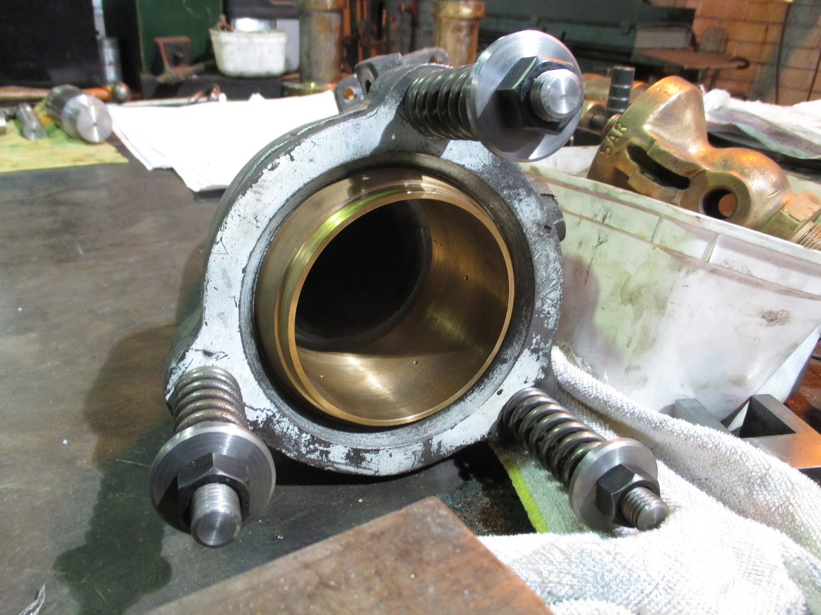
The 2 flexible steam and exhaust pipe ball joints have been overhauled, worn parts built up and re-machined, holes re-tapped, and new studs, washers and pins made. Drawings for the steam pipe expansion joints are complete and ready for manufacture.
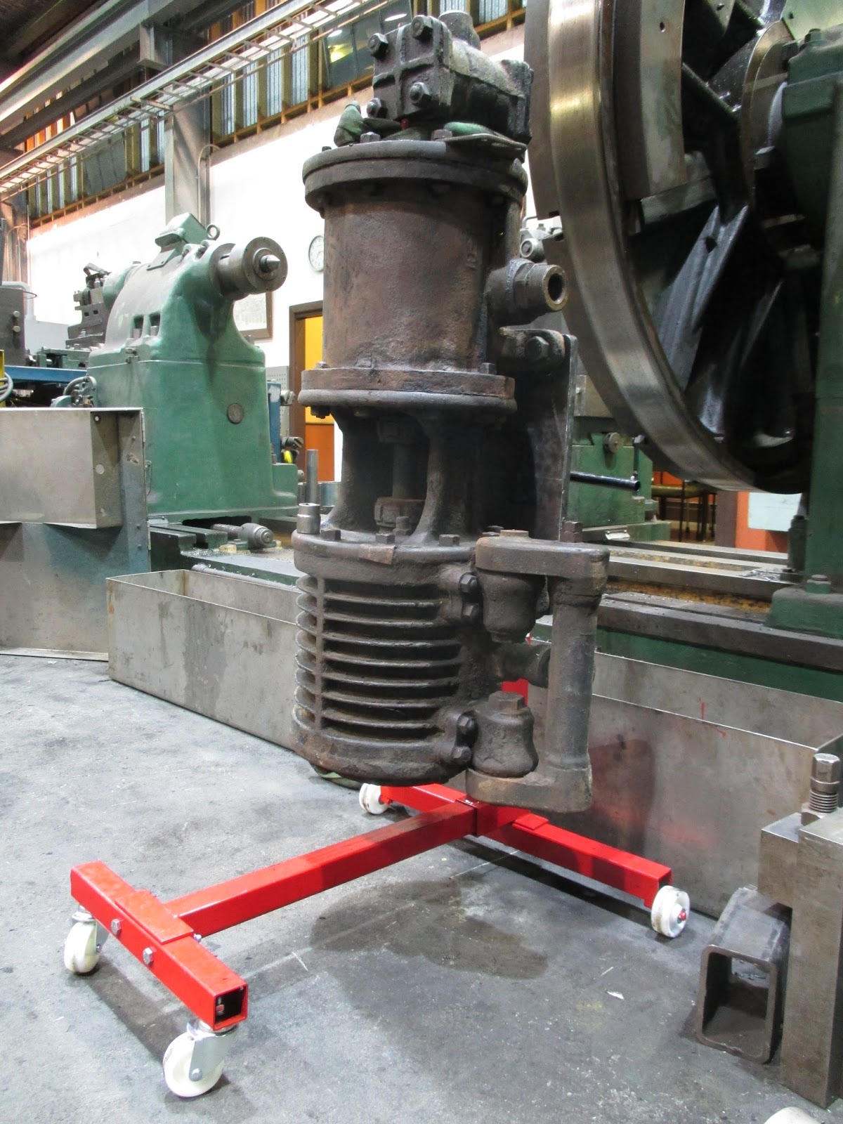
Recently purchased, an automotive engine stand has been modified to hold air compressors ready for overhaul
Work is currently progressing in the area of the weighshafts, including machining new lifting links from profile cut blanks.


Setting up and machining the weighshaft brackets to enable them to be aligned correctly on the engine units.


The original NG/G16 Garratt drawings specify drawgear springs by Spencer Moulton and, although now located in France, the company still exists. Not only that, but they were able to supply us new rubber springs, to the same specification, modified from standard parts they now produce for the SNCF, the French state railways! These parts have now been delivered.
Incidentally, for those with an interest in old cars, Alex Moulton (of Spencer Moulton) is better known for developing the rubber cone suspension first used famously in 1959 on Sir Alec Issigionis’ triumph of automotive genius, the Mini!


Most of the new components for the regulator and operating linkage has been manufactured, including valve and body castings, stuffing box and gland, operating shaft, and all the links and pins that fill the gaps.
Also seen below is the new handbrake shaft lever.

The engine unit centre pivot assembly model is complete and drawings of all the components finished. Current work entails assembling original parts to check fits & clearances, whilst also machining any new parts required.


Volunteer working parties continue, held on the 3rd Saturday of each month, with all the sand boxes and linkage being overhauled, and reverser stand modifications made to fit the revised shape of the boiler cradle frame rear section. The team are now marking, cutting and drilling footplate mounting angles in preparation for fitting all the new footplate sections.
