")
Sparks! The bane of any steam railway in the summertime, and, in bush fire prone Victoria, Puffing Billy is certainly no exception. With progressively longer and drier summers we are seeing our fire danger season extended year on year.
Luckily, a history of good engineering design has resulted in our locomotives starting fewer and fewer fires; all are spotted and quickly dealt with by the patrols which follow every train during the fire season.

This doesn’t mean that we don’t get any, however, and it appeared that there was one locomotive, 6A, which was developing itself a bit of a reputation for starting fires from the ashpan. With a ‘D’ exam looming, we decided to bring the engine in early, and see what we could do to solve the problem.

For those unfamiliar with the NA class locomotives, they are the same as nearly all narrow gauge engines; there is next to no room anywhere to make modifications, and any changes have a flow-on effect on other neighbouring components which have to be carefully considered.
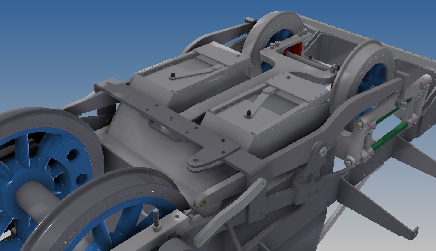
The hardest past of fitting a hopper ashpan is that there is an ‘A’ frame which sits below the ashpan and controls the movement of the trailing pony truck, leaving practically nowhere to squeeze in the hopper slides.

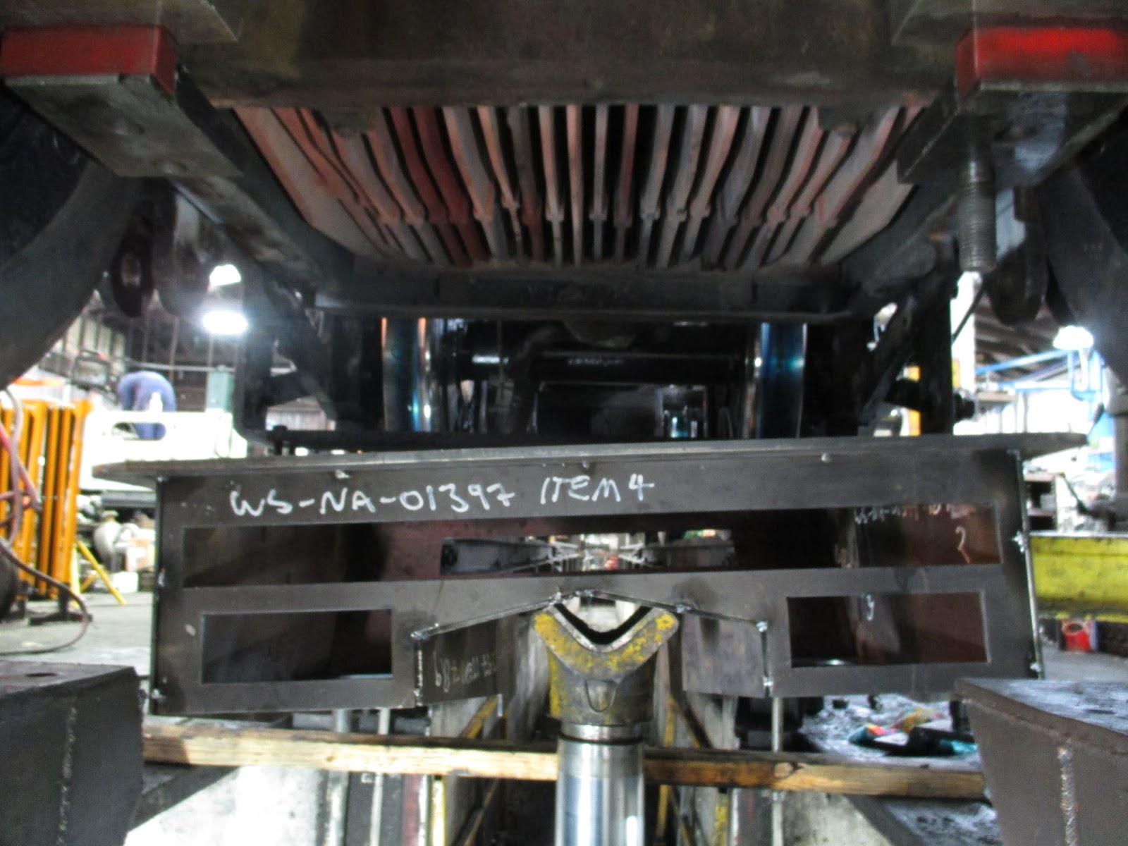
With a bit of work, we designed a T-shaped frame which had the same structural characteristics as the original ‘A’ frame, whilst no longer obstructing the bottom of the ashpan. The blank (below), once machined, will be a direct replacement for the existing ‘A’ frame, as will the ashpan, allowing them to be swapped with the existing parts with no modifications to the locomotive.


This is how a flat pack ashpan is delivered (above)! Below, all the components are seen laid out on the workshop floor. From our CAD models, cutting profiles of all the required plates were created, laser cut, and bends added where required.


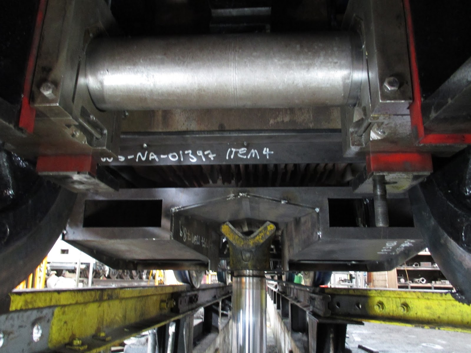
In order to replicate the interface between ashpan and the foundation ring on the boiler, an ashpan top plate was cut to be the same size as the existing one. It was drilled to match the studs on the foundation ring, and notched to clear the rear compensating beam brackets.

Once the parts had been tacked together, the ashpan was jacked up to meet the foundation ring using our hydraulic wheel drop pit.

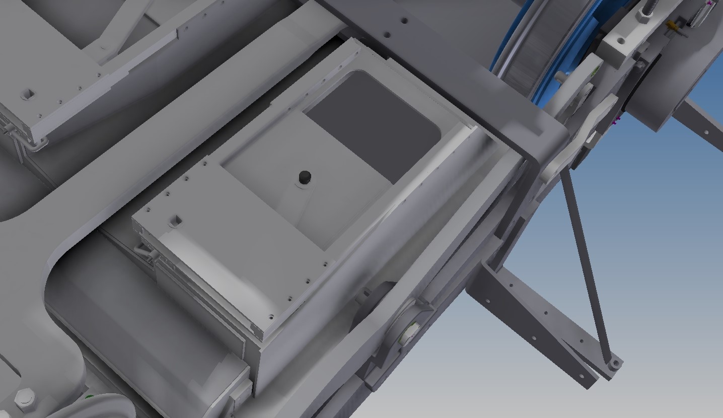
With the ashpan sitting in position, the air-boxes were added, and clearances checked all round.

In position, from outside, showing how much more capacity for ash it will have, compared to the original design.

Below, the detail shows the air-box design on the rear of the ashpan. The design forms an up-swept duct into which the primary air is drawn, with a damper covering the top to regulate the air flow.


As 6A is going through the usual ‘D’ exam as well, a lot of other work is also being carried out. Above, the old diving wheel tyres have been cut off, and the wheelsets are cleaned up ready for new tyres to be fitted (below).

Below, the rivets which secure the pony truck tyre retaining rings are being drilled out, prior to cutting the tyres off.

In order to make maintenance and replacement of parts easier, new standard drawings for all components of the NA locomotives are being created. As and when parts on the engines require replacement, new parts will be made to the standard drawings, with the long term aim of making all wearing parts the same across the fleet. Eventually this will mean being able to hold spares on the shelf, reducing downtime during repairs and exams.
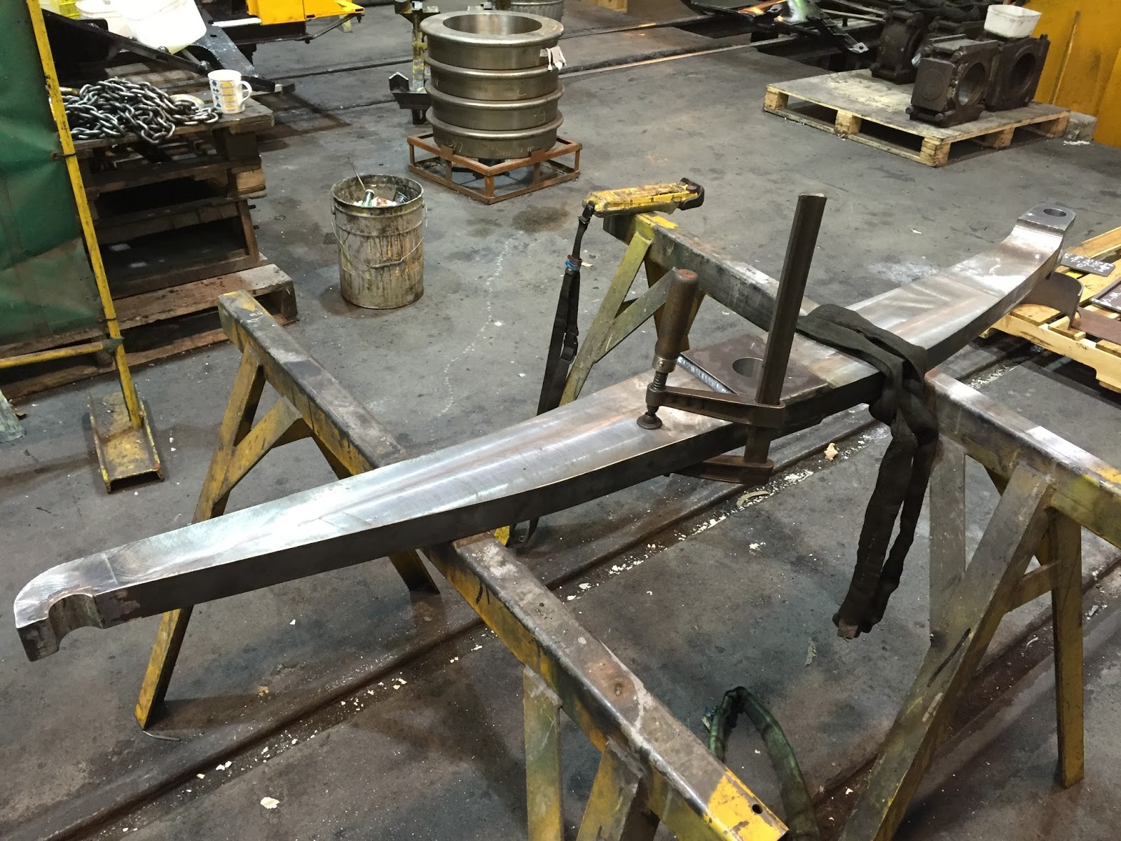
During the exam, the front compensating beam on 6A was found to require replacement; below, the new one nears completion, just awaiting painting and the fitting of new hardened bushes.
And finally, to give an idea of the amount of work involved in a ‘D’ exam, here is 6A in semi-stripped state, and on the track in front, many (but not all) of the parts which need to be removed as part of the exam process!
